Panels
Turns z-stacks of fluorescent beads into the measured 3D PSF model the Spline 3D fitters use, and for a split camera into two models and the transformation between the halves.
A 3D fit needs to know what one molecule looks like at every height. On a real microscope that image – the point spread function, PSF – is not a textbook Gaussian: a cylindrical lens stretches it, the objective adds its own aberrations, and both differ from one microscope to the next. The reliable way to know it is to measure it.
This window measures it from beads: sub-diffraction fluorescent beads stuck to a coverslip, imaged while the objective is stepped through focus. Each bead gives a small 3D image of the PSF (a bead stack). The window finds the beads, cuts them out, aligns them onto one another, averages them, smooths the average and turns it into a cubic-spline model – the experimental-PSF method of Li et al. 2018. The model is saved as an .h5 file, which the Spline 3D fitter reads; how the fit uses it is explained on that page.
It has two modes (mode):
What it needs:
It opens from Tools > Bead calibration... (or Dual-colour calibration..., which starts in the dual-colour mode), from the button of the same name on the Localize tab, or on its own as smappy-calibrate.
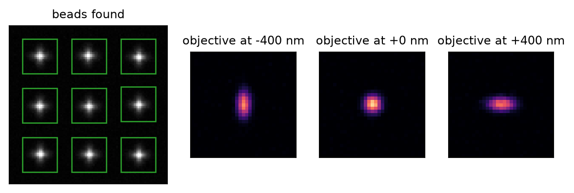
1. Find the beads. The stack is collapsed to its brightest value per pixel (a maximum projection), smoothed, and every local maximum clearly above the background noise (threshold, in multiples of the noise) is a bead. A bead too close to the image edge is dropped, and so are both beads of a pair closer than min distance: two overlapping PSFs are not one PSF.
2. Cut them out. Around each bead a box of ROI size pixels (plus a margin, padding, for the alignment to shift into) is cut from every plane. One background value is subtracted from the whole box – the median of its border pixels over all planes, so that the PSF's faint tails, which change with z, are kept – and the box is divided by the light in its brightest plane, so that a bright and a dim bead count alike. A bead whose brightness is far from the others' (brightness range) or that reaches the camera's maximum (saturation) is set aside: it is either two beads, a clump, or clipped.
Left: the maximum projection of a simulated bead stack, with the beads that were found (boxes, the size of the ROI). Right: one bead's box at three heights of the objective – the astigmatic spot is stretched one way below focus and the other way above.
3. Align them. The beads do not sit at the same place in their boxes, nor at the same height on the coverslip, so each is shifted in x, y and z until it matches a reference – the average of the half of the beads that look most alike. The shift is found by 3D cross-correlation, first over the whole stack, then refined over the planes around the centre (alignment range, iterations), and is applied with sub-pixel, sub-plane precision. A bead that has to move further than max xy shift or max z shift is taken for a misdetection and dropped.
4. Reject the odd ones out. Every aligned bead is compared with the average of all the others (so it cannot vouch for itself). A bead whose shape differs much more than the typical bead's does (rejection (MAD)) is left out of the average: a bead with a neighbour, a tilted one, a speck of dirt. The bead table lists every bead with its shift, its similarity to the others and why it was used or not.
5. Average and smooth. The accepted beads are averaged. The average still carries the noise of a finite number of photons, which a spline would faithfully reproduce as ripples, so it is smoothed along z (smoothing z; laterally only if smoothing xy is set), clipped at zero and scaled so that its brightest plane holds exactly one photon. A fitted photon number is then the photons in the molecule's in-focus image. Only the planes that every accepted bead covers after its z shift are kept.
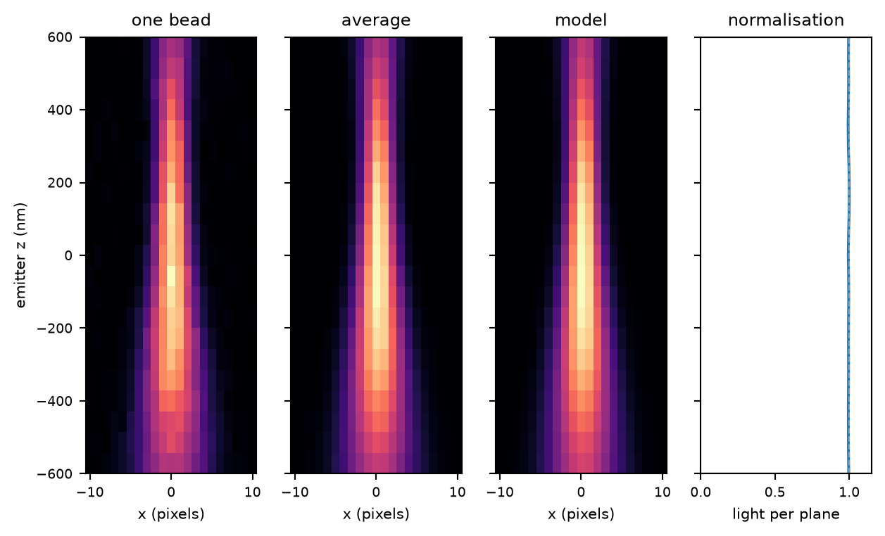
Left: side views (x against emitter z) of one bead as it was cut out, of the aligned average of the accepted beads, and of the smoothed model the fitter uses; the spot is narrow in x on one side of focus and wide on the other. Right: the light in each plane of the model – nearly constant in z, since a bead loses little light out of the box, and 1 in the brightest plane by construction.
6. The spline. The model is interpolated with cubic polynomials between the grid points, so that the fitter can evaluate it, and its slopes, at any sub-pixel position and height. This is what Save calibration... writes.
7. Check it. Calculate fit quality fits the calibration's own beads, plane by plane, with the same fitter the data will meet, and compares the fitted z with the objective's position. A good calibration gives a straight line of slope 1. The check is on the beads that made the model, so it shows that the model is self-consistent, not how precise a fit of dim molecules will be.
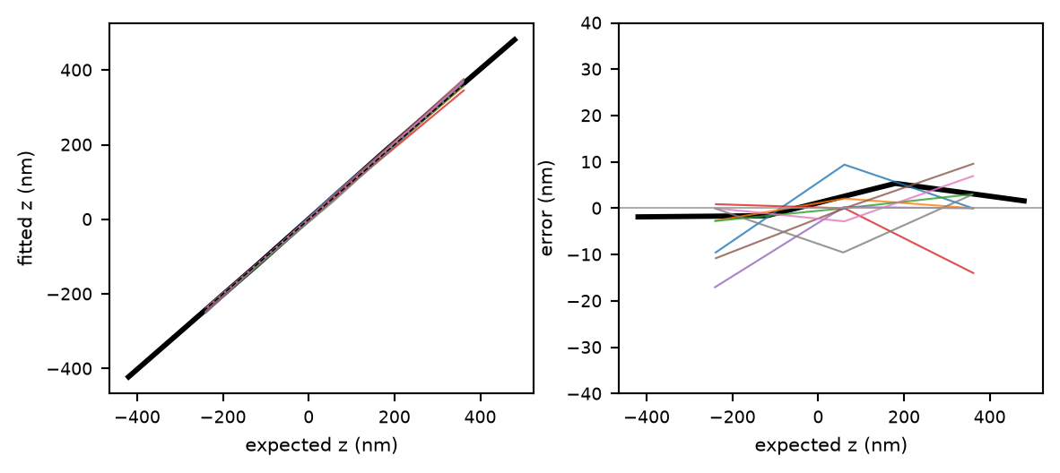
The calibration's own beads refitted plane by plane (thin lines, one per bead) and the averaged stack (black): fitted z against where the objective was. Right: the same after removing each bead's own offset – the part that says whether the model is distorted along z.
Dual colour: two halves, one calibration. The frame is cut at the split position into the main half (main channel) and the other, the secondary. Steps 1 and 2 run in each half on its own. Then:
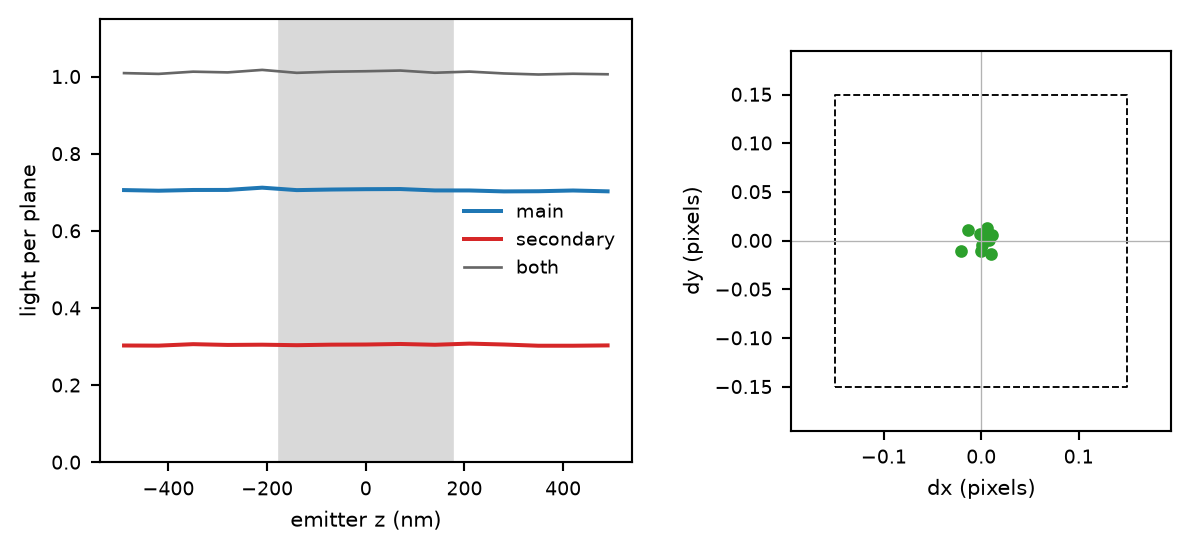
Dual colour. Left: the light in each plane of the two models; the grey band is the five planes around the stack's centre over which the two together are set to one photon, so the main half (70 % of the beads' light in this simulation) and the secondary (30 %) keep their share. Right: how far each bead pair lands from its partner after the transformation, in pixels; the box is the dx/dy limit a pair must meet.
Detection. With  the maximum projection smoothed by a Gaussian of width detection sigma, a pixel is a bead if it is a
  local maximum and

 the threshold: 1.4826 times the median absolute deviation estimates the noise's standard deviation without being pulled up by the beads. The bead's position is the centre of mass of its maximum, rounded to a pixel.
Extraction. A box of  pixels (
 the ROI size,
  the padding) is cut from every plane;
  , the median of its outermost pixels over all planes, is subtracted, and the box
  is divided by its brightness
  , the light of its brightest plane
  . The brightness limits are
  and
and  , with
  the median over unsaturated beads and
  the brightness range, so the brightest accepted bead is at most
  times the dimmest. Stacks of different lengths are cropped to the shortest, centred.
Alignment. A shift is the maximum of the normalised linear (not circular) cross-correlation
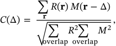
each lag normalised by the energy in the part of the two volumes that actually overlap at that lag, so an edge contributes nothing it does not have. The search is within a central  pixel window laterally. The integer peak is refined to a fraction of a pixel and a plane from the correlation itself, without resampling the bead:
  is taken, over one fixed overlap, at the 27 whole-voxel lags around the peak, the triquadratic through their logarithms (every
  with
with  ) is found, and its maximum within
  voxel is the shift. The logarithm, because the peak is close to a Gaussian; the triquadratic rather than a quadratic, because at 20 nm steps the peak is some two hundred times flatter along z than across, and its z curvature changes with the lateral offset (an astigmatic PSF's width changes with z) – a quadratic folds that change into the z shift and pulls every bead towards a whole plane. On simulated beads at 20 nm steps the shifts come back within 1.4 nm rms in z and 0.004 pixels laterally. Maximising the correlation of a linearly interpolated bead, as this did before, took nine times as long and left 5.7 nm: interpolation smooths by an amount that depends on the fraction, and draws the optimum towards whole planes. The first pass covers the whole stack; the median shift is subtracted, so that max xy shift and max z shift are measured from the consensus of the beads and not from the reference; the refinement passes (iterations minus one) correlate the central planes only,
  of them,
  the alignment range. Every bead is resampled once, with cubic interpolation, from its original box by its accumulated shift.
Shape score. Each bead is scaled to the current average  by
by  over the brightest quarter of
  's voxels (four passes), and compared with the average of the other accepted beads,
  :
:
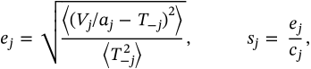
 their correlation coefficient (the table's correlation, and
  its residual). Dividing by
  keeps a bead that is broadly wrong but locally smooth from scoring well. A bead is kept if
  ,
,  the rejection (MAD), where the mean and standard deviation are taken over the beads within 4 MAD of the median when there are at least six. This is repeated three times after the last alignment pass.
The model. With  the average of the accepted, aligned beads over the planes all of them cover and the central
  pixels,

 a Gaussian of standard deviation smoothing z
  planes along z and smoothing xy pixels laterally (reflected at the edges). The spline coefficients are the not-a-knot cubic interpolant along x, then y, then z; the file stores them with the model, the unsmoothed average, every bead's shift and the reasons. z = 0 is the centre plane of the cropped stack, and the convention is that of the fitter: z is where the emitter is relative to the focal plane, in objective nanometres.
Dual colour: the normalisation. Both averages are smoothed the same way. Before clipping, each half's light is read as the mean plane sum over the centre plane and FOCAL_PLANES = 2 planes either side,

so that the two models together hold one photon around focus and keep the beads' ratio. Each also stores its share,  , as
, as photon_normalization. Fitted with one photon number for both halves (biplane), that number is the molecule's total; fitted with a number per half (two colours), each is multiplied by its  to give that half's photons. The light is counted before clipping because clipping keeps the noise in the tails above zero, and counted as light that noise read the photons about 1.5 % high; counted before, it averages out. Several planes are used so that one plane's noise does not set the scale, and few enough that light defocusing out of the box does not. The lowest value the spline takes between knots, relative to its peak, is stored as
 spline_minimum (the fitter floors its model for that).
Dual colour: pairs. A bead's position is the elliptical Gaussian fit (75 iterations) to the mean of the central 11 planes, 13 by 13 pixels; a fit that fails or lands more than 4 pixels off rejects the bead. The offset between the halves is voted for in a histogram of 2-pixel bins of every difference between a main-half and a secondary-half bead of the same stack, smoothed; pairs are mutual nearest neighbours within 12 pixels of each other after that offset, and never cross stacks. Fewer than min pairs stops the calibration.
Dual colour: the transformation. In homogeneous coordinates the map is  (
( a
a  matrix, secondary to main, in chip pixels). Round one: RANSAC (Fischler & Bolles 1981) – 500 draws of four pairs (a fixed seed, so it is reproducible), each solved by the normalised direct linear transform, keeping the draw with the most pairs within RANSAC radius; the inlier set is refitted until it stops changing, and then refined by least squares on the reprojection error in the main half with the robust soft-L1 loss
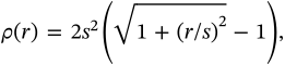
 half the dx/dy limit, which is quadratic for small errors and grows only linearly for large ones. Round two keeps the round-one inliers whose
  and
and  are both within the dx/dy limit and fits again on that fixed set. The map must not cross infinity anywhere on the camera image, forwards or backwards. The PSFs never enter this fit: a pair rejected for its shape still counts for the transformation, and the transformation list and the PSF list are kept apart (the table's state says which a pair is in).
Dual colour: the paired stacks. The secondary box is mirrored if the layout is, and shifted by the sub-pixel difference between where it was cut and where the transformation puts the partner of the main box – a shift, not a projective warp of the image. Both halves are divided by one number, the sum of their brightnesses, and then aligned with one  shift per pair: the correlation adds each half's numerator and energies, never correlating one half with the other. A pair whose correction exceeds the padding is kept for the transformation but not the PSF. The secondary model is mirrored back to the camera's orientation before it is saved.
Fit quality. Single channel: every fifth plane of each accepted bead (ROI of ROI size minus 4 pixels, the camera values restored) and of the average stack, fitted with the spline fitter from five z starts, keeping the best likelihood. Dual colour: the pairs fitted with the two-channel global fit, x, y and z shared, one z per pair (Li et al. 2022), which also shows the fitted split of the photons. The centred error removes each bead's median error, since a bead's absolute height on the coverslip is not known; it measures how distorted the z scale is, not how accurate.
Compared with the paper. The method is that of Li et al. 2018: beads registered in 3D, averaged, and interpolated by cubic splines. The main changes are those listed under Differences from SMAP: a Gaussian smoothing in place of a smoothing B-spline, a linear correlation, a leave-one-out shape rejection, and the joint normalisation of the two halves.
The files or folders of bead z-stacks (TIFF or OME-TIFF). All stacks are pooled into one calibration, so they must share the z step.
Adds stacks one by one.
Adds a folder; with search subdirectories ticked, every acquisition found inside it.
Removes the selected entries from the list.
Whether Add folder... looks for acquisitions inside the folder's subfolders, or adds the folder as it is.
Single channel or Dual colour. Switching keeps the files and the settings the two modes share, clears the result, and shows or hides the split-camera settings; the Transformation and Field diagnostics pages exist only in dual colour.
The calibration's settings. The common ones are shown; more has the rest, whose defaults rarely need changing.
The model's width, in camera pixels; odd, at least 7. It must hold the spot at the ends of the z range, where it is widest: too small cuts off the tails, too large lets neighbouring beads in. The fitter's ROI may be smaller.
Leave it on auto when the files record the step. A wrong step stretches or squeezes every fitted z by the same factor.
Lower it if clear beads are missed, raise it if noise or dim debris is detected; 6 is a good start for bright beads.
Larger than twice the half-width of a defocused bead's spot, or the tails of a neighbour end up in the model. Beads closer than this are both dropped, so dense fields lose many beads.
The width of the smoothing along z. About one to two z steps is usual. Too little leaves noise ripples that become stripes in z; too much blurs the PSF's change with z and costs z precision.
Extra pixels around the ROI for the alignment to shift into; must exceed max xy shift by more than one pixel.
The smoothing before detection; about the spot's width.
Beads that need a larger lateral shift than this are rejected.
Beads that sit further than this from the others in height are rejected: a bead stuck higher up, or one the correlation mismatched.
The z range around the centre that the refinement correlates over. Around the focus the PSF has most structure, far from it least.
The number of alignment passes: one coarse, then refinements.
The shape cut, in standard deviations of the beads' scores (see In detail). Smaller rejects more beads, larger keeps more.
Lateral smoothing in pixels; 0, the default, is usually right, because the beads' alignment already averages laterally.
The fewest accepted beads the calibration will be built from. Fewer than ten gives a warning in any case.
The largest ratio between the brightest and the dimmest accepted bead, centred on the median; auto disables the check.
The camera value at which a bead counts as saturated; auto takes the file's integer maximum (65535 for 16-bit).
How the camera chip is split: right-left or up-down, and whether the secondary half is mirrored along the split (an image splitter with an odd number of mirrors in one path). Look at a bead frame: if the pattern of beads in one half is the other's mirror image, choose a mirrored layout.
Which half is the reference that positions are reported in. It must match the layout: left/right for right-left, upper/lower for up-down.
The first pixel of the second half; auto is the middle of the image.
The fewest bead pairs the transformation may be fitted from; at least 4, which is what a projective map needs. More pairs, spread over the field, make the map reliable towards the edges.
The first round's tolerance, in pixels. It only has to separate right pairings from wrong ones, so it can be generous.
The second round's tolerance on each axis, in pixels. Good bead data sits well below 0.1 pixel; if too few pairs pass, look at the Transformation page before raising it.
Runs everything: detection, extraction, alignment, rejection, the model (and in dual colour the pairs and the transformation). It runs in the background; the status bar says how many beads were used.
Refits the beads with the model just built and draws the Fit quality page.
Writes the calibration as .h5, by default named after the bead data's folder and saved beside it. Opened from the main window, saving also puts it into the fitter's calibration field – Spline 3D for a single-channel calibration, Spline 3D 2C for a dual-colour one.
Puts the calibration last saved into the fitter again, for when the field was changed since. In dual-colour mode the button says Spline 3D 2C.
Opens the averaged bead stack – the raw average, before smoothing, so that a bad bead or a misalignment still shows – slice by slice in its own window; in dual colour both halves side by side.
The stack's projection with its beads (green used, red rejected), the brightness of every bead against its lateral shift with the accepted brightness band, a side view of the model, and each bead's shape residual against its z shift. In dual colour: the split frame with its pairs, and the main half's field with pairs used for the PSF and the transformation (green), for the transformation only (orange), rejected (red) and unpaired beads. Select a bead in the table to see its own stack.
Dual colour: how far each pair lands from its partner after the transformation (round two), and the first round's residuals with the dx/dy limit box. A tight, round cloud centred on zero is good; a cloud with a tail or two clusters means wrong pairs or the wrong layout.
After Calculate fit quality: fitted against expected z for every bead and for the average, the centred error, and the lateral and axial profiles of the beads against the model. Good: a straight line of slope 1 over the useful range and a centred error of a few nanometres; the ends of the range, where the spot is faint and wide, are always worse. Dual colour adds the fitted photon split, secondary over total, which should be flat in z at one half: the models already carry the beads' split.
Dual colour: the main half's beads overlaid with the transformed secondary ones, and how the beads' shape mismatch varies over the field. A mismatch that grows towards one side is a PSF that changes over the field, which one model cannot describe.
Dual colour: per half, brightness against lateral shift, and the shape residual against the z shift and against the correlation, coloured by what each pair was used for.
Marks the selected beads in the table as excluded (or includes them again); space does the same. Takes effect on Recalculate.
Builds the calibration again from the beads already found, without the excluded ones. In dual colour it refits the transformation too.
Based on SMAP's bead calibrator, calibrate3D_GUI_g in fit3Dcspline (calibrate3D_g and getstackcal_g for one channel, calibrate_globalworkflow for two; Ries 2020). The main changes:
photon_normalization), so a fit with the photons linked (biplane) returns the molecule's total and a fit with a number per half returns each half's photons.